


Need a Mechanical Clutch? Here’s How to Choose the Right Option
Mechanical clutches and mechanical clutch-and-pump assemblies provide a practical way to engage or disengage a hydraulic pump from an engine, motor or power take-off system. They are used where hydraulic power is needed on demand, without requiring the pump to remain driven continuously.
Although the two product types perform a similar overall job, they are not supplied in the same way. A mechanical clutch is selected to suit a compatible hydraulic pump, while a mechanical clutch and pump assembly includes a gear pump that has already been paired with the clutch.
Quick answer
Choose a standalone mechanical clutch when you already have a suitable pump or need to specify the pump separately. Choose a complete clutch-and-pump assembly when you want a more convenient matched package with a stated pump group, displacement and flow rate. In both cases, the input speed, power, rotation, mounting and hydraulic requirements must be checked before ordering.
Mechanical clutches
A flexible choice for customers who need to connect an existing or separately selected hydraulic gear pump to a suitable mechanical drive.
Mechanical clutch-and-pump assemblies
A clutch and hydraulic gear pump supplied together, helping simplify pump matching and making the intended hydraulic output easier to compare.
- 1) What is a mechanical clutch?
- 2) What is a mechanical clutch-and-pump assembly?
- 3) What is the main difference?
- 4) Where are mechanical clutches used?
- 5) What do Group 1, Group 2 and Group 3 mean?
- 6) How do flow and pressure affect selection?
- 7) Why do rotation and speed matter?
- 8) How should the clutch be operated and maintained?
- 9) What information is needed before ordering?
- 10) Frequently asked questions
1. What Is a Mechanical Clutch?
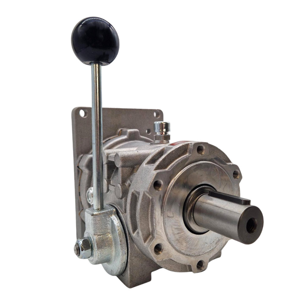
A mechanical clutch is a power-transmission component positioned between a driving source and a hydraulic pump. Its purpose is to allow the pump drive to be engaged when hydraulic power is required and disengaged when the hydraulic function is not in use.
The driving source could be an engine, gearbox, motor or suitable power take-off arrangement. When the clutch is engaged, torque is transferred to the pump shaft. The pump can then draw oil from the reservoir and create hydraulic flow for the connected equipment.
| Part of the system | Purpose |
|---|---|
| Engine, motor or PTO drive | Supplies the mechanical input power. |
| Mechanical clutch | Engages or disengages the drive transmitted to the hydraulic pump. |
| Hydraulic gear pump | Converts the mechanical input into hydraulic oil flow. |
| Hydraulic circuit | Uses the oil flow to operate cylinders, motors and other hydraulic functions. |
A clutch does not create hydraulic pressure by itself
The clutch transfers mechanical power to the pump. The pump produces oil flow, while pressure develops when that flow meets resistance from the load in the hydraulic circuit.
2. What Is a Mechanical Clutch-and-Pump Assembly?
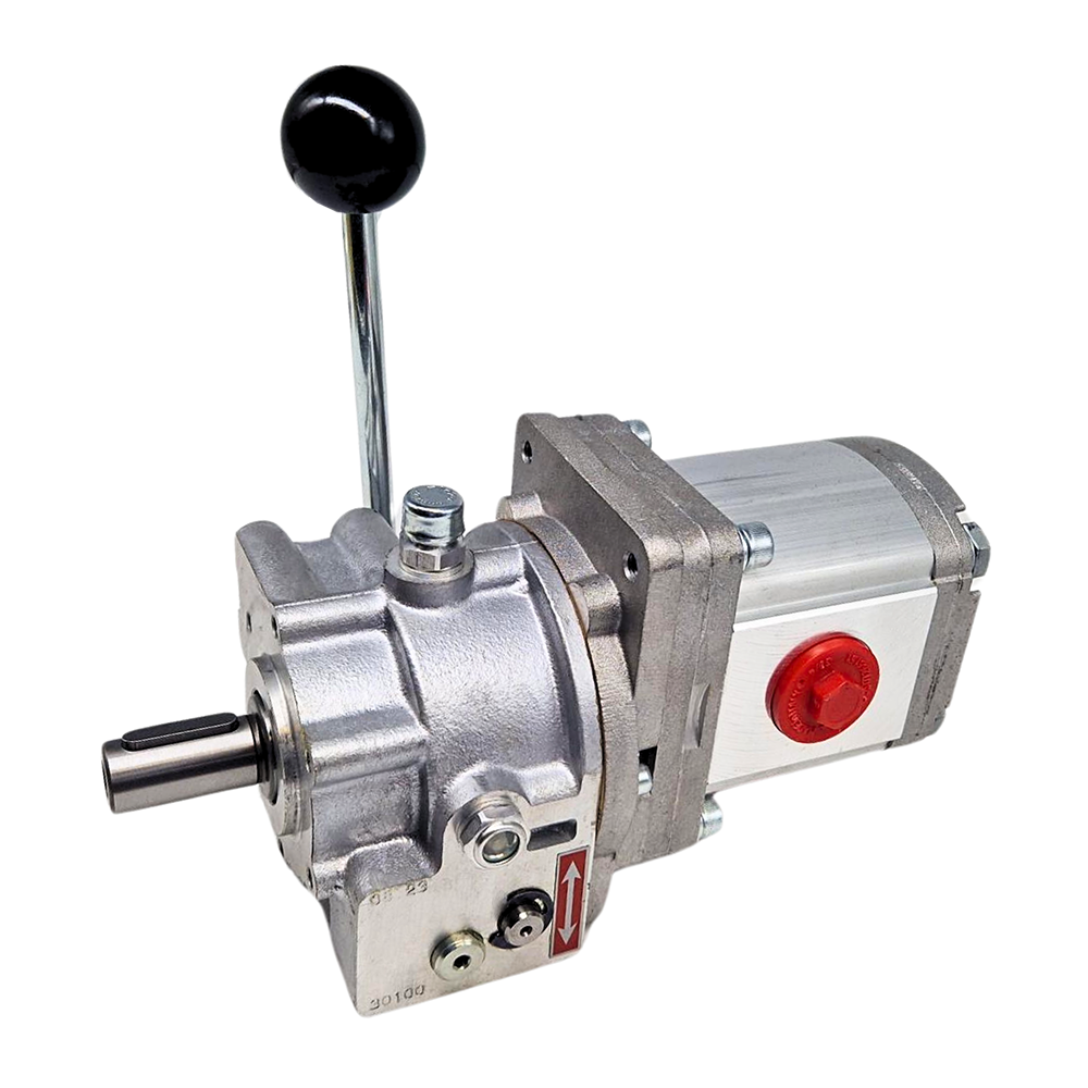
A mechanical clutch-and-pump assembly combines the clutch with a hydraulic gear pump. Instead of selecting the clutch and pump as separate components, the customer receives a package with a specified pump group, displacement and expected flow at the stated operating speed.
This can make selection more straightforward, particularly when the required hydraulic output is known. It also reduces the number of mechanical compatibility checks compared with pairing a clutch and pump independently.
Matched components
The pump mounting and clutch interface have already been paired as part of the supplied assembly.
Clearer hydraulic output
Pump displacement and flow information make it easier to compare assemblies against the machine's requirements.
Fewer separate items
Ordering a complete package can reduce the risk of selecting an incompatible clutch and pump combination.
Multiple pump sizes
Assemblies are available with different pump groups and displacements for a range of hydraulic duties.
Matched does not mean suitable for every machine
A complete assembly simplifies component matching, but it must still suit the available drive power, input speed, direction of rotation, hydraulic flow, working pressure, mounting arrangement and duty cycle.
3. What Is the Difference Between a Mechanical Clutch and a Clutch-and-Pump Assembly?
The main difference is whether the hydraulic pump is included. This affects how much flexibility the customer has, how many compatibility checks are required and how the hydraulic output is selected.
| Consideration | Mechanical clutch only | Mechanical clutch-and-pump assembly |
|---|---|---|
| Hydraulic pump included? | No. A compatible pump must be supplied or selected separately. | Yes. The clutch and gear pump are supplied together. |
| Selection flexibility | Greater flexibility to choose a particular pump, displacement or port arrangement. | Choice is based on the available preconfigured assembly specifications. |
| Compatibility checks | Pump group, flange, shaft, rotation, speed, torque and mounting must be matched. | The pump-to-clutch interface is matched, but the complete assembly must suit the machine. |
| Best suited to | Replacement projects, custom systems or installations where a pump is already available. | New installations or customers wanting a convenient clutch-and-pump package. |
| Hydraulic output | Depends on the separately selected pump and its operating speed. | Published displacement and flow figures help identify the intended output. |
Which option is better?
Neither is automatically better. The standalone clutch provides more freedom when building or repairing a system, while the complete assembly can make purchasing and installation planning simpler.
4. What Are Mechanical Clutches and Clutch-and-Pump Assemblies Used For?
These products can be used in many hydraulic systems where pump drive is needed only when a particular function is operating. The exact clutch and pump specification will depend on the equipment, available drive arrangement and required hydraulic performance.
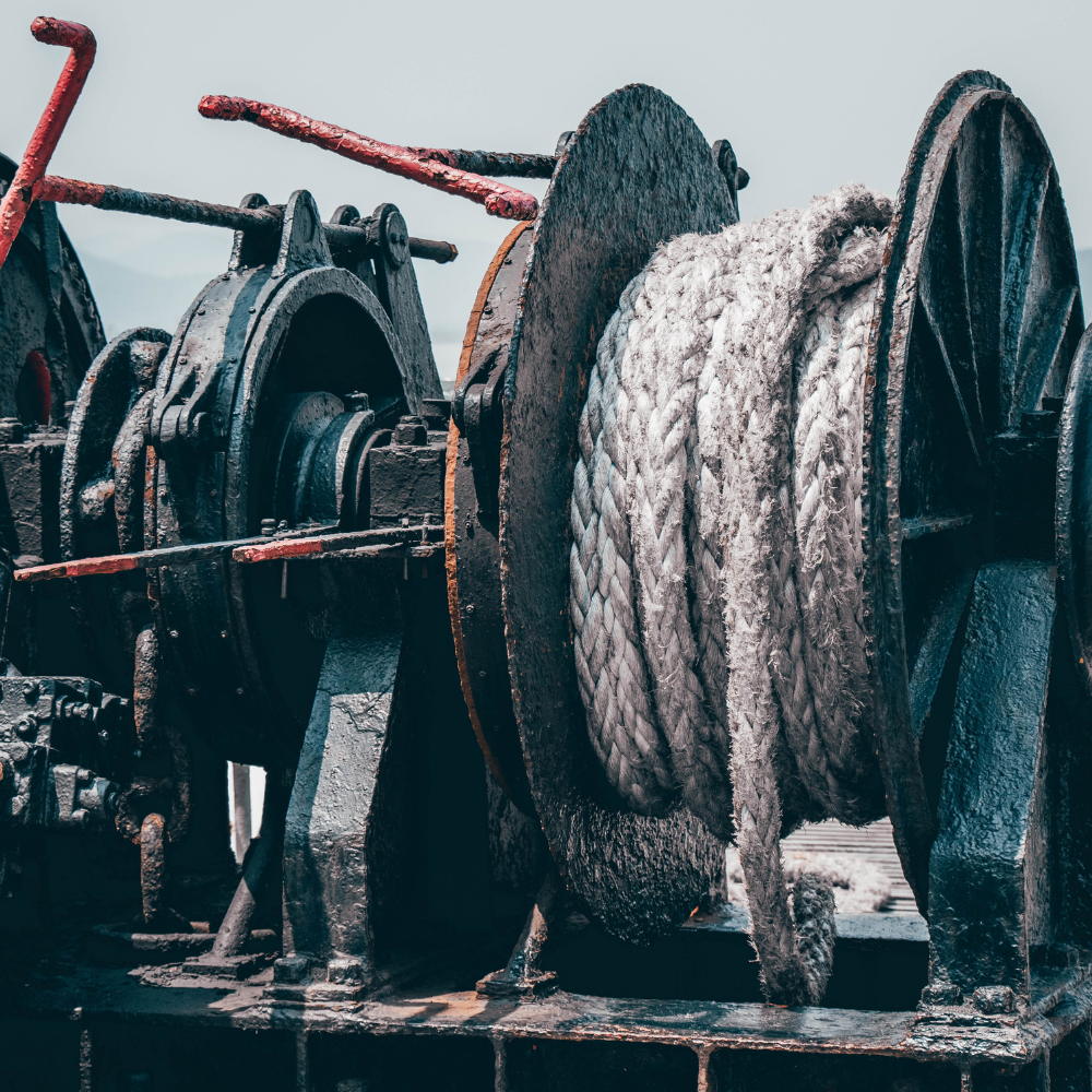
Vehicle recovery and winches
A clutch-driven pump can provide hydraulic power for recovery winches, vehicle-mounted winches and other intermittent pulling functions.
Agricultural machinery
Suitable systems may power auxiliary hydraulic functions on spreaders, feeders, trailers, crop-handling equipment and other farm machinery.
Forestry and timber equipment
Applications can include forestry winches, log-handling equipment, hydraulic trailers, splitters and other mobile timber-processing functions.
Construction and mobile plant
Mechanical clutch assemblies can support tipping, lifting, stabilising and auxiliary hydraulic circuits where the pump does not need to run continuously.
Marine deck equipment
Correctly specified systems may be used for deck winches, capstans, hauling equipment and other hydraulically operated marine functions.
Service and utility vehicles
Vehicle-mounted hydraulic equipment can include cranes, access functions, loading equipment, recovery systems and workshop or maintenance attachments.
Industrial machinery
Clutch-driven pumps may be used for presses, conveyors, handling equipment, test rigs and machinery that requires hydraulic power at selected stages of operation.
Custom hydraulic power systems
They can also form part of a purpose-built hydraulic system driven by a suitable engine, motor, gearbox or PTO arrangement.
Application examples are not a substitute for system design
The clutch, pump, reservoir, valves, hoses, filtration, relief protection and drive arrangement must all be sized for the specific machine. Confirm suitability before installation.
5. What Do Group 1, Group 2 and Group 3 Hydraulic Pumps Mean?
Hydraulic gear pumps are commonly divided into groups based on their physical frame size, shaft and mounting standard. Mechanical clutch-and-pump assemblies may therefore be described as Group 1, Group 2 or Group 3.
The group number helps identify the pump's physical format, but it does not tell you the complete performance of the pump. Two pumps in the same group can have different displacements, flow rates, pressure limits and power requirements.
| Pump group | General characteristic | Selection consideration |
|---|---|---|
| Group 1 | Compact pump frame for lower-displacement requirements. | Useful where installation space and lower hydraulic output are important. |
| Group 2 | Common medium-size format covering a broad range of displacements. | Often selected for general mobile, agricultural and industrial hydraulics. |
| Group 3 | Larger pump frame commonly available with higher displacements. | May suit higher-flow duties, provided the drive has sufficient power and space. |
The group number is not a quality grade
A Group 3 pump is not automatically better than a Group 1 or Group 2 pump. The correct group is the one that fits the clutch and installation while providing the required hydraulic performance.
6. How Do Flow Rate and Pressure Affect the Choice?
Flow rate and pressure perform different jobs in a hydraulic system. The pump's flow rate, normally stated in litres per minute, influences how quickly a hydraulic cylinder or motor operates. Pressure develops when the oil flow meets resistance and determines the force or torque available from the actuator.
| Hydraulic value | What it affects | What can happen if incorrectly selected |
|---|---|---|
| Flow rate | The operating speed of hydraulic cylinders and motors. | Too little flow can make functions slow; excessive flow can cause poor control, restriction and heat. |
| Working pressure | The force or torque available to move the load. | Insufficient pressure may not move the load; excessive pressure can damage components or create a hazard. |
| Pump displacement | The volume of oil moved per pump revolution. | An unsuitable displacement can produce the wrong flow at the available drive speed. |
| Hydraulic power | The combination of flow and pressure that the drive must supply. | The clutch, pump or prime mover may be overloaded if the required power is too high. |
Basic hydraulic power estimate
Hydraulic power (kW) = pressure (bar) × flow (L/min) ÷ 600
This is a theoretical estimate. Real installations require additional allowance for mechanical and hydraulic efficiency losses. Always compare the result with the rated clutch, pump and drive power.
Do not choose from the highest figure alone
The highest flow, pressure or power rating is not automatically the best option. Select the assembly that meets the machine's requirements without exceeding the ratings of the clutch, pump or hydraulic circuit.
7. Why Do Direction of Rotation and Input Speed Matter?
The clutch must suit the direction in which the drive turns, and the hydraulic pump must rotate in its specified direction. Using an incompatible pump rotation can prevent correct oil delivery and may damage the pump.
Input speed is equally important. Pump flow increases with pump speed, but every clutch and pump has maximum operating and engagement limits. Excessive speed can increase wear, heat and mechanical loading.
| Check | Why it matters |
|---|---|
| Clockwise or anti-clockwise rotation | The selected clutch-and-pump combination must match the actual direction of the driving shaft. |
| Reversible operation | Only use reversible operation where the individual clutch and complete installation permit it. |
| Normal input speed | Determines pump speed, expected flow and mechanical loading. |
| Engagement speed | The clutch must be engaged and disengaged within the stated product limits. |
| Available power and torque | The drive must supply the required hydraulic output without exceeding the clutch rating. |
Engage the pump under the correct conditions
For Flowfit mechanical clutch-and-pump products, engagement and disengagement should be carried out with the directional valve in the unload position and within the limits stated for the individual model. Check the product instructions rather than applying one speed limit to every installation.
8. How Should a Mechanical Clutch Be Operated and Maintained?
Correct lubrication, controlled engagement and routine inspection are important for reliable service. Maintenance requirements can vary between models, so the individual technical information should always be followed.
- Add the specified lubricant before use. Do not assume that a new mechanical clutch has been supplied ready to run. Flowfit product instructions for this range specify the required gear oil.
- Engage with the hydraulic circuit unloaded. Removing hydraulic load during engagement helps reduce shock loading on the clutch, pump and drive.
- Remain within the permitted speed. Check both the continuous operating speed and the maximum engagement or disengagement speed.
- Inspect the oil level and condition. Look for loss of lubricant, contamination, overheating or unusual noise.
- Check mounting and alignment. Loose fixings, poor support or misalignment can place avoidable loads on shafts, bearings and housings.
- Inspect the hydraulic circuit. Restricted suction lines, blocked filters or a relief valve operating continuously can cause heat and create additional load on the pump.
- Follow the product-specific service interval. Record operating hours and change the lubricant at the interval specified for the selected clutch.
Signs that require investigation
Unusual noise, excessive temperature, difficult engagement, oil leakage, reduced hydraulic output, vibration or rapid lubricant deterioration should be investigated before the equipment is returned to service.
9. What Information Do I Need Before Ordering?
Start with the machine's required hydraulic performance and the available mechanical drive. Collecting the information below will make it much easier to identify whether a standalone clutch or a complete clutch-and-pump assembly is the better choice.
| Information to collect | Why it is needed |
|---|---|
| Application and machine type | Establishes the function, operating environment and likely duty cycle. |
| Required flow in L/min | Helps determine the pump displacement needed at the available speed. |
| Normal and maximum pressure | Confirms the hydraulic load and approximate power requirement. |
| Input speed | Allows pump output and clutch operating limits to be checked. |
| Direction of rotation | Ensures the clutch and pump are configured for the driving shaft. |
| Available drive power and torque | Confirms that the engine, motor or PTO can support the intended hydraulic output. |
| Pump group and mounting | Required when matching a standalone clutch to a separate gear pump. |
| Pump displacement | Determines the theoretical oil volume produced per revolution. |
| Shaft, flange and coupling details | Confirms mechanical compatibility with the existing drive and pump. |
| Continuous or intermittent duty | Helps assess heat, lubrication, reservoir capacity and service requirements. |
| Available installation space | Ensures the complete unit can be mounted, supported and maintained safely. |
Choose a clutch only when...
You already have a compatible pump, are replacing a clutch or need a specific pump configuration that is not supplied as a standard assembly.
Choose an assembly when...
You want the clutch and pump supplied together and can select a standard package that meets the required displacement, flow, pressure and drive conditions.
10. Mechanical Clutch and Pump Assembly FAQs
Can I fit any hydraulic pump to a mechanical clutch?
No. The pump group, flange, shaft, direction of rotation, permitted speed and power requirement must match the clutch. Check the technical drawings and specifications for both components.
Does a clutch-and-pump assembly arrive ready to install?
The clutch and pump are supplied as a matched combination, but installation still requires the correct drive connection, mounting, hydraulic reservoir, hoses, valves, filtration, relief protection and lubricant. Check the individual product instructions before operation.
Can the hydraulic pump run continuously?
That depends on the ratings of the selected clutch, pump and complete hydraulic system. Continuous operation creates more heat and places greater demands on lubrication, reservoir size, filtration and cooling.
Does a larger pump group always produce more flow?
No. A larger group can accommodate larger pump sizes, but actual flow depends on the selected displacement and pump speed. Compare the stated L/min figure rather than selecting by group alone.
Will a higher-pressure pump make the equipment move faster?
Not necessarily. Operating speed is mainly affected by oil flow. Pressure relates to the resistance of the load and the force or torque required to move it.
Can I change the direction of rotation?
Rotation options depend on the individual clutch and pump. Flowfit offers reversible clutch products and clockwise or anti-clockwise configurations within the range, but the exact model must be confirmed before ordering.
Why should the valve be unloaded when engaging the clutch?
Engaging with the pump unloaded reduces the torque shock transmitted through the clutch and drive system. It also helps prevent the pump from starting immediately against hydraulic pressure.
Do mechanical clutches require oil?
Products in this Flowfit mechanical clutch range require the specified gear oil before use. Follow the lubrication grade, filling method, inspection interval and oil-change schedule stated for the selected model.
What should I provide when asking Flowfit for help?
Provide the application, required flow, normal and maximum pressure, input speed, direction of rotation, available power, pump group, pump displacement, mounting details and expected operating time.
Choosing the Right Mechanical Clutch or Clutch-and-Pump Assembly
The correct product is the one that matches both sides of the installation: the mechanical drive and the hydraulic circuit. Selecting only by pump group, maximum power or product size can result in incorrect flow, excessive loading or an incompatible mounting arrangement.
Before ordering, confirm:
- Whether you need a standalone clutch or a complete clutch-and-pump assembly
- The required hydraulic flow and working pressure
- The pump displacement and pump group
- The drive speed and direction of rotation
- The available mechanical power and torque
- The shaft, flange, coupling and mounting arrangement
- The continuous or intermittent operating duty
- The required reservoir, hoses, valves, filtration and relief protection
- The correct lubricant and maintenance requirements
Compare Flowfit mechanical clutch products
Explore standalone mechanical clutches and complete clutch-and-pump assemblies for Group 1, Group 2 and Group 3 hydraulic pump applications.
Tip: Have the required flow, pressure, input speed, rotation, pump details and application information available when contacting the Flowfit technical sales team.
The total one-stop supplier for hydraulic components & systems
Get in touch

Parys Road
Ludlow
Shropshire
SY8 1XY


