


How to Choose the Right Agricultural PTO Pump Assembly
A complete agricultural PTO pump assembly combines a PTO gearbox with a matched hydraulic gear pump. It allows the tractor's power take-off to produce hydraulic oil flow for equipment such as tipping trailers, log splitters, fertiliser spreaders, crop machinery and other hydraulically operated implements.
Although many assemblies look similar, their performance can vary considerably. The correct choice depends on the pump group, pump displacement, gearbox ratio, flow rate, maximum working pressure, gearbox material and mounting arrangement.
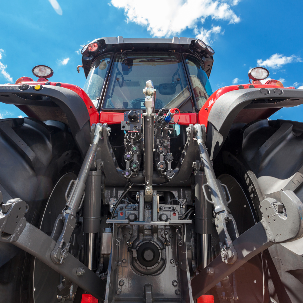
Group 2 PTO pump assemblies
Group 2 pumps provide a compact option for lower and medium-flow hydraulic applications. They can suit machinery where installation space, weight and moderate hydraulic output are important considerations.
Group 3 PTO pump assemblies
Group 3 pumps have a larger physical frame and are commonly selected where greater displacement, higher flow or increased power capacity is required.
Quick answer
Group 2 and Group 3 describe the physical size and mounting standard of the hydraulic pump. The gearbox ratio determines how quickly the pump turns in relation to the tractor PTO. Pump displacement and speed determine the flow rate, while the maximum pressure rating limits how much hydraulic pressure the assembly is designed to withstand. No single group, ratio or pressure rating is best for every machine.
- 1) How does a PTO pump assembly work?
- 2) Group 2 vs Group 3: what is the difference?
- 3) What do 1:3, 1:3.5 and 1:3.8 ratios mean?
- 4) How is the flow rate selected?
- 5) What does maximum working pressure mean?
- 6) Aluminium or cast-iron gearbox?
- 7) Why use a PTO gearbox fixing plate with chain?
- 8) PTO pump assembly selection checklist
- 9) Frequently asked questions
1. How Does an Agricultural PTO Pump Assembly Work?
The tractor engine turns the PTO shaft. The PTO shaft connects to the input of the gearbox, and the gearbox drives the hydraulic gear pump.
The pump draws hydraulic oil from a reservoir and delivers it into the hydraulic circuit. That oil can then operate cylinders, hydraulic motors, valves and other components fitted to the machinery.
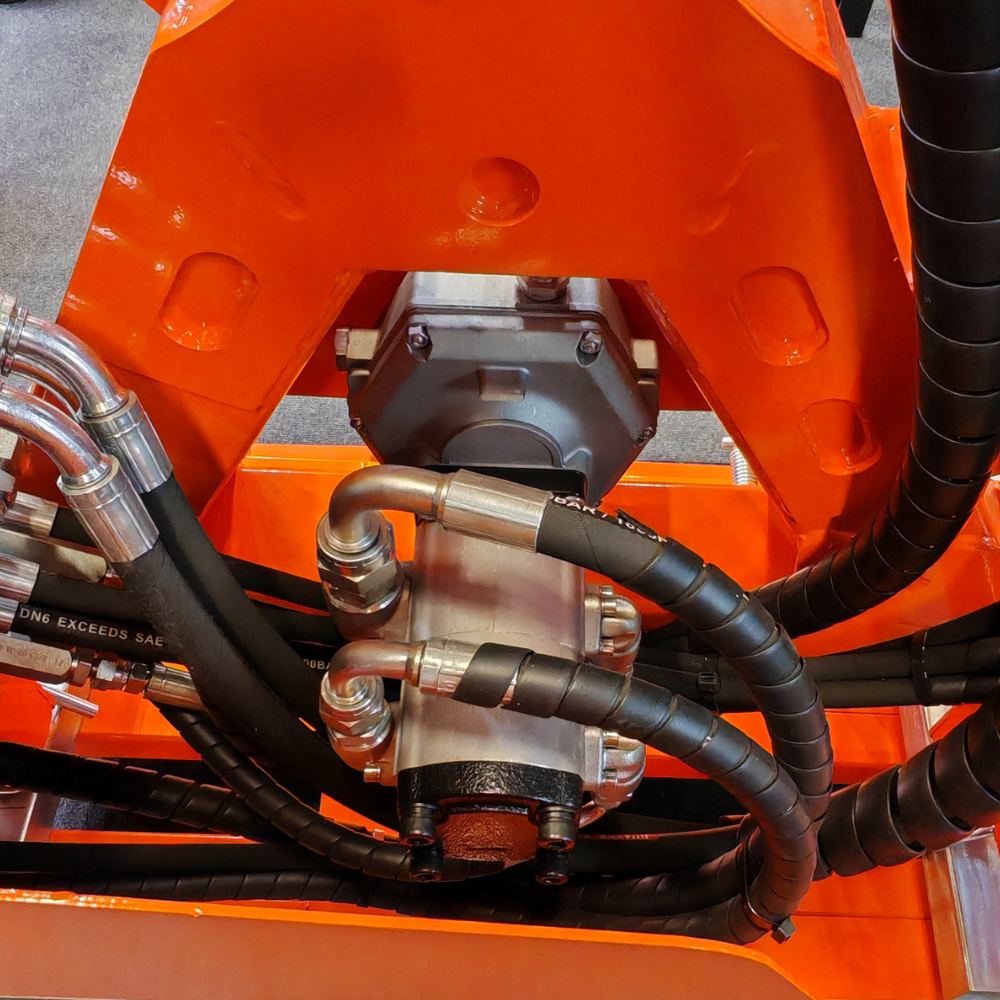
| Component | Purpose |
|---|---|
| Tractor PTO | Provides the mechanical input power for the assembly. |
| PTO gearbox | Changes the input speed and transfers power to the hydraulic pump. |
| Hydraulic gear pump | Produces the hydraulic oil flow required by the connected equipment. |
| Oil reservoir | Stores the hydraulic oil and supplies it to the pump inlet. |
| Control and relief valves | Direct oil through the circuit and help prevent excessive hydraulic pressure. |
| Fixing plate and chain | Help support, locate and restrain the assembly when specified for the installation. |
Flow and pressure are different
The hydraulic pump produces oil flow. Pressure develops when that flow meets resistance from the load. The pump does not continuously produce its maximum rated pressure unless the hydraulic system requires it.
2. Group 2 vs Group 3 PTO Pumps: What Is the Difference?
Group 2 PTO pump assemblies and Group 3 PTO pump assemblies use different hydraulic pump frame sizes, shaft dimensions and mounting standards.
The group number is not a quality grade. A Group 3 pump is not automatically better than a Group 2 pump. The correct group is the one that provides the required displacement, flow, pressure and power capacity while fitting the available installation space.
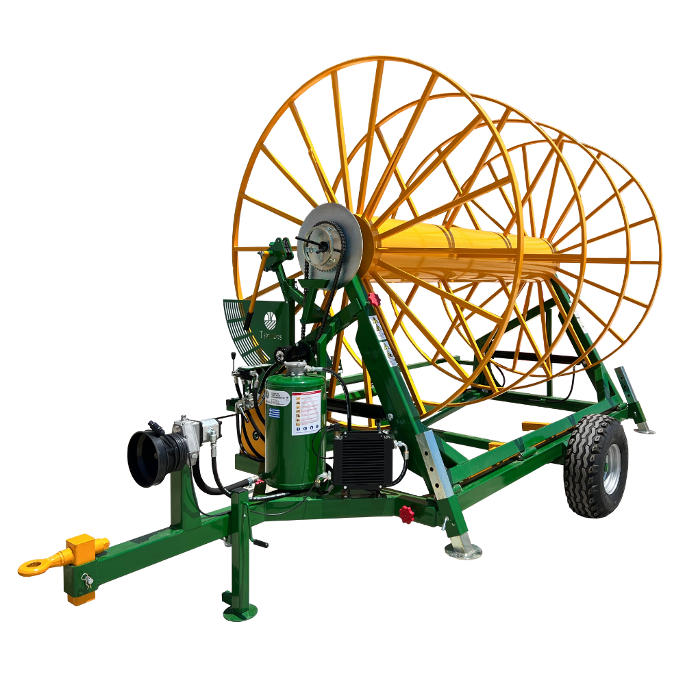
| Consideration | Group 2 pump assembly | Group 3 pump assembly |
|---|---|---|
| Physical size | More compact pump frame. | Larger and heavier pump frame. |
| Typical displacement | Generally selected for lower and medium displacement requirements. | Generally selected where larger pump displacement is required. |
| Typical flow requirement | Often suitable for lower and medium-flow auxiliary circuits. | Often suitable for higher-flow agricultural and mobile equipment. |
| Installation space | May suit more restricted mounting areas. | Requires additional space and suitable support. |
| Power demand | Can suit applications with a more moderate hydraulic power requirement. | Can accommodate higher-flow applications that may require more PTO power. |
| Best choice | Choose when its displacement, flow and pressure ratings match the machine. | Choose when the application genuinely requires its larger capacity. |
Example Group 2 configurations
Depending on the pump displacement and gearbox ratio, Group 2 assemblies can cover a wide range of outputs.
| Gearbox ratio | Pump displacement | Specified flow | Maximum working pressure |
|---|---|---|---|
| 1:3 | 8 cc/rev | 13.00 L/min | 270 bar |
| 1:3 | 16 cc/rev | 26.00 L/min | 225 bar |
| 1:3.8 | 16 cc/rev | 32.90 L/min | 180 bar |
| 1:3.8 | 20 cc/rev | 41.10 L/min | 140 bar |
View all Group 2 agricultural PTO pump assemblies
Example Group 3 configurations
Group 3 assemblies can provide larger displacements and higher flow rates for more demanding hydraulic applications.
| Gearbox ratio | Pump displacement | Specified flow | Maximum working pressure |
|---|---|---|---|
| 1:3 | 25 cc/rev | 40.50 L/min | 225 bar |
| 1:3 | 38 cc/rev | 61.60 L/min | 190 bar |
| 1:3.5 | 25 cc/rev | 47.30 L/min | 250 bar |
| 1:3.5 | 50 cc/rev | 94.50 L/min | 125 bar |
View all Group 3 agricultural PTO pump assemblies
Do not select by pump group alone
Two pumps from the same group can have very different displacements, flow rates and pressure ratings. Always compare the complete assembly specification rather than choosing only from the Group 2 or Group 3 label.
3. What Do 1:3, 1:3.5 and 1:3.8 PTO Gearbox Ratios Mean?
The gearbox ratio describes the relationship between the tractor PTO input speed and the speed of the hydraulic pump.
In these step-up gearbox configurations, the pump turns faster than the PTO shaft. At a nominal tractor PTO speed of 540 rpm, the approximate pump speeds are:
| Gearbox ratio | Approximate pump speed at 540 rpm PTO | General effect |
|---|---|---|
| 1:3 | 1,620 rpm | Provides three pump revolutions for each PTO revolution. |
| 1:3.5 | 1,890 rpm | Produces more pump speed and flow than 1:3 when the same displacement is used. |
| 1:3.8 | 2,052 rpm | Provides the highest pump speed of these three ratios at the same PTO input speed. |
A higher gearbox ratio can increase the flow produced by a particular pump displacement, but it can also increase power demand, noise, heat generation and sensitivity to inlet restrictions.
The selected ratio must therefore be suitable for the pump's permitted speed, the tractor PTO speed and the required hydraulic output.
A higher ratio is not automatically better
A 1:3.8 assembly may produce more flow than a 1:3 assembly using the same pump displacement, but excessive flow can make equipment operate too quickly and can create avoidable heat. Match the output to the machine rather than selecting the largest ratio available.
4. How Is the PTO Pump Flow Rate Selected?
Flow rate is normally stated in litres per minute, or L/min. It affects the operating speed of hydraulic cylinders and hydraulic motors.
The theoretical flow of a gear pump can be estimated using the pump displacement and pump speed:
Basic flow calculation
Flow in L/min = pump displacement in cc/rev × pump speed in rpm ÷ 1,000
For example, a 25 cc/rev pump turning at approximately 1,890 rpm has a theoretical output of about 47.25 L/min. This corresponds closely with a specified product flow of 47.30 L/min.
Published product data should always be used for final selection because actual output can be affected by pump efficiency, oil temperature, pressure and operating conditions.
| Flow condition | Possible result |
|---|---|
| Flow is too low | Cylinders and motors may operate more slowly than required. |
| Flow is correctly matched | The equipment can operate at its intended speed with manageable heat and pressure loss. |
| Flow is too high | Functions may become difficult to control, while hoses and valves may create excessive restriction and heat. |
More flow is not always better
Select the flow required by the machinery manufacturer. Do not choose a larger pump simply to obtain the highest possible L/min figure. The reservoir, hoses, valves, filters, cylinders and motors must all be sized for the selected flow.
5. What Does Maximum Working Pressure Mean?
Maximum working pressure is the highest hydraulic pressure for which the assembly is rated under the specified conditions. It is a product limit, not a recommendation to operate continuously at that pressure.
The hydraulic system should normally operate below its maximum component ratings and should include a correctly specified pressure-relief valve.
The pressure rating of the pump assembly must also be considered alongside the ratings of:
- Hydraulic hoses and fittings
- Control valves
- Hydraulic cylinders and motors
- Filters and filter housings
- Quick-release couplings
- Pressure gauges
- Reservoir connections
| Example assembly | Specified flow | Maximum working pressure | What the figures demonstrate |
|---|---|---|---|
| Group 2, 1:3, 8 cc/rev | 13.00 L/min | 270 bar | A lower-flow option with a comparatively high pressure rating. |
| Group 2, 1:3.8, 20 cc/rev | 41.10 L/min | 140 bar | Greater flow, but with a lower maximum pressure rating. |
| Group 3, 1:3.5, 25 cc/rev | 47.30 L/min | 250 bar | A medium-flow Group 3 configuration with a high pressure rating. |
| Group 3, 1:3.5, 50 cc/rev | 94.50 L/min | 125 bar | A high-flow option intended for an application with a lower maximum pressure requirement. |
These examples show why an assembly should not be chosen from flow or pressure alone. Hydraulic power demand rises when either flow or pressure increases, and the tractor must be capable of supplying the required PTO power.
How to Estimate the PTO Gearbox Power Requirement
The theoretical hydraulic power required by a PTO gearbox-and-pump assembly can be estimated using:
Power (kW) = pressure (bar) × flow rate (L/min) ÷ 600
For matched Flowfit assemblies, we use a more conservative calculation than the theoretical ÷ 600 figure. This provides additional allowance for efficiency losses and real-world operating conditions, helping keep the selected pressure-and-flow combination within the gearbox power rating.
Standard gearbox power ratings within this range:
- Group 2 gearbox: up to 10 kW
- Group 3 aluminium gearbox: up to 20 kW
- Group 3 cast-iron gearbox: up to 37 kW
Always check the individual product specification. The selected pressure-and-flow combination must remain within the ratings of the gearbox, pump and complete hydraulic system.
Do not set the system from the pump rating alone
The relief pressure must protect the complete hydraulic circuit. It should be based on the machinery requirements and the rating of the lowest-rated suitable component, not simply the maximum figure printed for the pump assembly.
6. Aluminium or Cast-Iron PTO Gearbox?
PTO pump assemblies can be supplied with either an aluminium or cast-iron gearbox. Both materials can provide dependable service when the gearbox is correctly matched, mounted and operated.
| Consideration | Aluminium gearbox | Cast-iron gearbox |
|---|---|---|
| Weight | Lighter and generally easier to handle during fitting and removal. | Heavier, requiring suitable support and careful handling. |
| Installation | Can suit mobile machinery where reducing assembly weight is useful. | May suit fixed or demanding installations where additional mass is acceptable. |
| Rigidity | Provides a practical lightweight housing for many agricultural applications. | Provides a highly rigid housing and may be considered for demanding mechanical duties. |
| Handling | Usually easier to position during installation. | May require additional lifting or mounting support. |
| Selection | Choose according to the stated ratio, pump group, pressure, power and mounting requirements. | Choose according to the stated ratio, pump group, pressure, power and mounting requirements. |
Cast iron should not automatically be selected because it appears stronger, and aluminium should not automatically be selected because it is lighter. The individual product ratings and the intended duty cycle are more important than the housing material alone.
Compare the complete specification
Check the maximum input power, gearbox ratio, pump speed, pump group, working pressure and permitted mounting arrangement. Two gearboxes made from the same material may have different performance limits.
7. Why Use a PTO Gearbox Fixing Plate With Chain?
A complete PTO gearbox and pump assembly has its own weight and produces a reaction force when torque is transmitted through the gearbox.
A compatible PTO gearbox fixing plate with chain can provide a more secure and controlled mounting arrangement than allowing the assembly to remain unsupported.
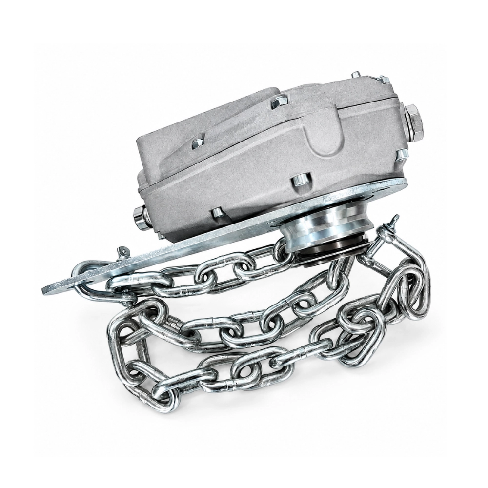
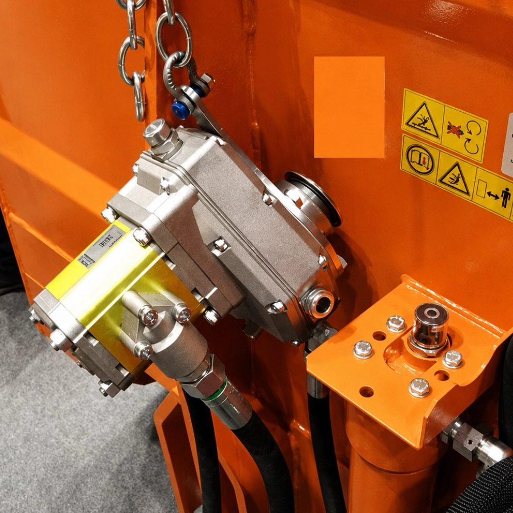
Supports the assembly
The fixing plate helps carry and locate the gearbox-and-pump unit rather than leaving its full weight acting through the PTO connection.
Helps control unwanted movement
The correctly positioned chain provides a restraint against reaction movement when the PTO starts, stops or operates under load.
Reduces strain on connections
A stable mounting arrangement can help reduce avoidable bending, movement and vibration at the gearbox, pump, hoses and PTO connection.
Makes installation more consistent
A product designed for the gearbox can provide a clearer mounting method than a fabricated or improvised support.
| Benefit | Why it matters |
|---|---|
| Improved support | Helps prevent the assembly from hanging unsupported from the PTO shaft. |
| Controlled restraint | Helps limit gearbox movement caused by torque reaction. |
| More stable hose routing | Reduces movement at the pump ports and helps keep hoses away from rotating parts. |
| Easier inspection | Provides a defined mounting arrangement that can be checked before operation. |
| Matched accessory | Allows the mounting product to be selected alongside the complete pump assembly. |
Use the correct fixing product
Confirm that the fixing plate and chain are compatible with the selected gearbox and tractor installation. Fit them in accordance with the supplied instructions. The fixing chain does not replace the required PTO guarding, PTO guard restraint or other safety equipment.
A useful addition to a complete assembly
Ordering the appropriate fixing plate with chain at the same time as the gearbox-and-pump assembly can reduce the risk of reaching installation day without a suitable method of supporting and restraining the unit.
8. Agricultural PTO Pump Assembly Selection Checklist
Begin with the hydraulic requirements of the equipment rather than selecting the largest pump or the highest pressure rating.
- Confirm the required flow. Check the machine manufacturer's stated L/min requirement or calculate the required cylinder or motor speed.
- Confirm the normal and maximum pressure. Establish the pressure needed to move the load and the maximum pressure permitted by the machine.
- Select the pump displacement. Match the cc/rev figure to the required output at the intended pump speed.
- Select the gearbox ratio. Compare 1:3, 1:3.5 or 1:3.8 according to the required pump speed and flow.
- Choose Group 2 or Group 3. Consider displacement, physical size, power capacity and mounting space.
- Check the tractor PTO connection. Confirm shaft type, spline arrangement, PTO speed and direction of rotation.
- Check the available PTO power. The tractor must be capable of supplying the required combination of flow and pressure.
- Choose the gearbox material. Compare aluminium and cast iron against weight, rigidity, mounting and duty requirements.
- Plan the mounting arrangement. Confirm whether the assembly requires a compatible fixing plate, support or chain.
- Check the complete hydraulic circuit. Size the reservoir, suction hose, pressure hose, return line, filters, valves and couplings for the selected output.
| Information to collect | Why it is needed |
|---|---|
| Tractor make and model | Helps identify the PTO shaft, PTO speed and available power. |
| Equipment being operated | Provides context for the duty cycle, load and hydraulic functions. |
| Required flow in L/min | Allows the pump displacement and gearbox ratio to be selected. |
| Normal working pressure | Helps confirm the required hydraulic force and power. |
| Maximum permitted pressure | Helps select a suitable assembly and relief-valve setting. |
| Operating time | Helps assess oil capacity, filtration and cooling requirements. |
| Available mounting space | Helps determine the suitable pump group and gearbox material. |
9. Agricultural PTO Pump Assembly FAQs
Can I replace a Group 2 pump with a Group 3 pump?
Not as a direct swap unless the gearbox, mounting, shaft, power capacity, rotation and hydraulic specification are designed for the Group 3 pump. The two groups use different physical dimensions.
Does a higher gearbox ratio increase hydraulic pressure?
Not directly. A higher ratio increases pump speed and can increase flow. Hydraulic pressure is created by resistance in the circuit and must remain within the assembly's pressure rating.
Which ratio produces the most flow?
When the same pump displacement and PTO speed are used, a 1:3.8 ratio produces more pump speed and theoretical flow than 1:3.5 or 1:3. The ratio must still remain within the pump's speed and power limits.
Should I choose the assembly with the highest maximum pressure?
Not necessarily. Choose an assembly that provides the required flow and has a suitable pressure rating for the machine. An unnecessarily high pressure rating does not improve equipment performance.
Is Group 3 always higher flow than Group 2?
Group 3 pumps are generally available in larger displacements, but the actual flow depends on both displacement and pump speed. Always compare the stated L/min figure.
Is cast iron always better than aluminium?
No. Cast iron offers additional mass and rigidity, while aluminium provides a lighter assembly. The correct material depends on the product ratings, mounting arrangement and operating duty.
Do I need a fixing plate and chain?
Many installations benefit from a compatible fixing plate and restraint because the assembly should not be left hanging unsupported from the PTO connection. Check the gearbox instructions and the requirements of the tractor installation.
Does the complete assembly include a fixing plate?
Not necessarily. Check the individual product description carefully. Where the fixing plate and chain are supplied separately, they should be selected and ordered alongside the assembly.
What causes a PTO hydraulic pump to overheat?
Common causes include excessive flow, a relief valve operating continuously, restricted hoses or filters, an undersized reservoir, incorrect oil viscosity, excessive pump speed or internal leakage.
What information should I provide when asking for help?
Provide the tractor PTO details, required flow, normal working pressure, maximum pressure, machinery type, operating time and available mounting space.
Choosing the Right Agricultural PTO Pump Assembly
The correct PTO pump assembly is the one that matches the hydraulic and mechanical requirements of the machine. Group size, gearbox ratio, flow rate, pressure and housing material must be considered together.
Before ordering, check:
- Group 2 or Group 3 pump size
- Pump displacement in cc/rev
- Required flow in L/min
- Normal and maximum pressure
- 1:3, 1:3.5 or 1:3.8 gearbox ratio
- Maximum permitted pump speed
- Available tractor PTO power
- PTO shaft and spline type
- Direction of rotation
- Aluminium or cast-iron gearbox
- Fixing plate, support and chain requirements
- Reservoir, hose, valve and filtration requirements
Compare agricultural PTO pump assemblies
View complete Group 2 and Group 3 PTO gearbox-and-pump assemblies in a range of ratios, displacements, flow rates, pressure ratings and gearbox materials.
Tip: Have the required flow, working pressure, PTO speed, machinery details and preferred mounting arrangement available when comparing assemblies.
The total one-stop supplier for hydraulic components & systems
Get in touch

Parys Road
Ludlow
Shropshire
SY8 1XY


